|
|
|
|
Aircraft Systems Topic 11.
Boeing 767 Flight Controls
| General
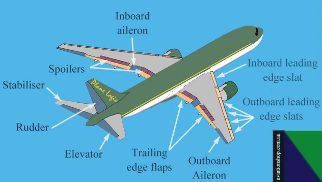
The B767 has 3 independent hydraulic systems which move the primary flight controls. There is no ‘manual reversion’ on the B767, as there is on the B727. The primary controls are the rudder, elevators, inboard ailerons, and outboard ailerons, as shown in blue on the attached diagram. Spoilers on the upper surface of the wing also assist the ailerons. The spoilers also act as ‘speedbrakes’ in the air, and as “liftdumpers” when on the ground. Ailerons High speed aircraft use both inboard and outboard ailerons at low speed to effect changes around the longtitudinal axis (roll). As speed increases an aileron lockout device gradually restricts the movement of the outboard ailerons, leaving the inboard types to effect roll at high airspeed. Speed signal inputs for this come from the Central Air Data Computer (CADC). Each aileron is powered by two hydraulic systems for redundancy purposes should one hydraulic system fail. The ailerons can be trimmed using trimming switches in the cockpit. This re-sets the aileron neutral point. Elevator The two elevator panels are each powered by all three hydraulic systems (left, centre and right), again for redundancy purposes. They are mounted at the rear of the stabiliser, and provide pitch control about the aircrafts lateral axis. Two elevator ‘Q feel’ systems provide artificial feel forces to the pilot control yokes. This is because hydraulic powered controls mask high demands that may be applied by pilots inadvertently. Rudder The single panel rudder is moved by actuators powered by all three hydraulic systems. A device called a ‘ratio changer’ de-sensitizes rudder deflection for a given rudder pedal force as speed increases. This ratio changer gets the speed inputs from the Central Air Data Computer (CADC). Swept wing aircraft such as the B767 are prone to a yawing/rolling combination when they encounter turbulence. This is called ‘Dutch Roll’. To counter this tendency the B767 rudder incorporates two separately powered hydraulic ‘Series Yaw Dampers’. These also assist in turn co-ordination, such that no rudder inputs are required by the pilot to provide a balanced (skid ball in the centre) turn. Unlike the ‘Parallel Yaw Dampers” fitted to some aircraft, the rudder pedals of the series system do NOT move in association with yaw damper inputs. The amount of deflection of the rudder panel by the yaw damper is reduced at high speed to avoid potential over-stressing of the airframe. The speed input from the CADC is blended with information from the yaw rate provided by the ‘Ring Laser Gyro’ (RLG) that is part of the Inertial Reference Navigation Unit (IRU). This ensures that just the correct amount of rudder is deflected to damp out any potential dutch roll before it builds up.
Spoilers There are 12 spoiler panels, 6 on the upper surface of each wing. Some of these move in-flight in association with the ailerons to provide roll control. The panels can also be used as speedbrakes in flight to slow the aircraft down and steepen the descent profile. On the ground all panels deploy as ‘Liftdumpers’ to spoil any residual lift at touchdown, avoid bouncing, and place more weight on the wheels to assist in wheel braking effort. Spoilers are controlled through a speedbrake lever which is to the left of the thrust levers. Flaps and Slats The B767 is provided with leading edge slats, and trailing edge flaps for high lift during takeoff and landing. The inboard ailerons also droop in conjunction with flap extension. Actuation of flaps and slats is normally from the centre hydraulic system, and a back-up actuation method is by electric drive motors, should the centre hydraulic system depressurise. The electric standby system takes considerably longer to drive the slats and flaps to the desired settings - about 3 minutes from zero to 20 flap. The B767 is fitted with a ‘Flap/Slat Asymmetry’ monitoring system which will stop the flaps being extended further should a situation develop where one wings high lift devices are extending at a different rate to the other. A ‘Load Relief’ monitoring system prevents any exceedance of the flap limit speed when the flaps are set to 25 (-300 aircraft), or 30 flap (-200 aircraft), by retracting the flap to the previous stage. The cockpit flap lever will NOT move when this happens. When speed is reduced below the limit speed, the flap will automatically extend to the previously selected setting. Stabiliser Trim As with most large high speed aircraft the horizontal stabiliser is used a one large trimming surface. Some advantages of such a system instead of a conventional system with a fixed horizontal surface with separate in-built elevator and trimming surfaces is that trim drag is reduced, and full elevator movement is available at full up or full down trim settings. Increased airspeed produces a decrease in the trimming rate. Under normal operations the stabiliser is moved by the centre and left hydraulic systems. Later mini editorials will address each of the sub-items above in greater detail, as questions are often asked by CASA in the ATPL Aerodynamics and Aircraft Systems examination on these systems. I trust this mini editorial is of assistance to you, and good luck with your examinations. Let’s be careful out there ! Best wishes Rob Avery ATPL Lecturer
|
![]()