|
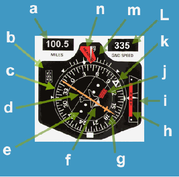
Item
a.
This shows the distance to the tuned
DME beacon.
Item b.
Indicates whether a VOR, or ILS frequency is tuned. The
DME will automatically be tuned to the DME station that
corresponds to the tuned ILS. When tuned in to a co-located
VOR/DME station, setting the VOR frequency (VHF) will
automatically tune in the DME (UHF).
Item c.
This is the compass rose, that is automatically aligned to
magnetic north at the aircraft location by the flux valve.
Item d.
This is the course deviation indicator (CDI). It tells the
pilot whether he is on the selected radial as set using the
"Course Arrow" (item g). If the aircraft is off
track the CDI will indicate how many degrees of error there
is. If the CDI bar is say off to the right, then the pilot
should turn the aircraft to the right in order to intercept
the selected course. If the CDI bar is off to the left, a left
turn is required to intercept the set course. The aircraft is
on the 345 VOR omni radial FROM the station. The bearing TO
the station is 165M.
Item e.
This is the scale that tells the pilot how many degrees
the aircraft is left or right of the set course. In this case
the aircraft is exactly on the 345 radial FROM the tuned VOR
beacon. The calibration of the scale is different for ILS and
VOR. When an VOR is tuned, each dot represents 2 degrees. When
an ILS is tuned, the dots each represent half a degree (ie: 4
times as sensitive).
Item f.
This advises the pilot whether the aircraft current heading is
toward or away from the beacon. Hence it is called the
"TO/FROM" flag. In this case the aircraft is flying
TOward the tuned VOR beacon as witnessed by the arrow (flag)
pointing TOward the front of the miniature aircraft symbol. If
the aircraft was flying away from the VOR beacon a flag would
be seen pointing rearward. It should be noted that the TO/FROM
flag is hidden from view when an ILS frequency is tuned.
Item g.
This is the "Course Selector Arrow", and it's
position on the compass rose reflects the value set on the VOR
tuning/selector panel.
Item h.
This red flag (sometimes red and white striped) indicates that
valid glideslope information is NOT being recieved, and so an
ILS can NOT be flown for fear of flying into the ground.
Item i.
This is the glideslope deviation scale. The centre of the
scale represents the aircraft, and the white marker represents
the position of the glideslope. If the glideslope marker is
below the centre of the scale, the aircraft is above the
glideslope, and vice versa if the glideslope marker is above
the centre datum.
Item j.
This flag indicates that valid VOR or Localiser signals are
NOT being received, and bearing information will be incorrect.
There should be no flags showing, except when the radio is
selected off, or the test button on the VOR tuning/selector
panel is pushed.
Item k.
This is the selected heading as set by the pilot in the
heading selector window, which in large aircraft is usually
located within the autopilot selector panel.
Item L.
Represents the aircraft current groundspeed as calculated from
the rate of closure to the tuned DME beacon.
Item m.
The value at the top of the compass arc is the aircraft
current magnetic heading.
Item n.
This flag indicates that valid signals are NOT being received
from the flux valve, and so heading information is corrupt,
and should not be used. |
|


